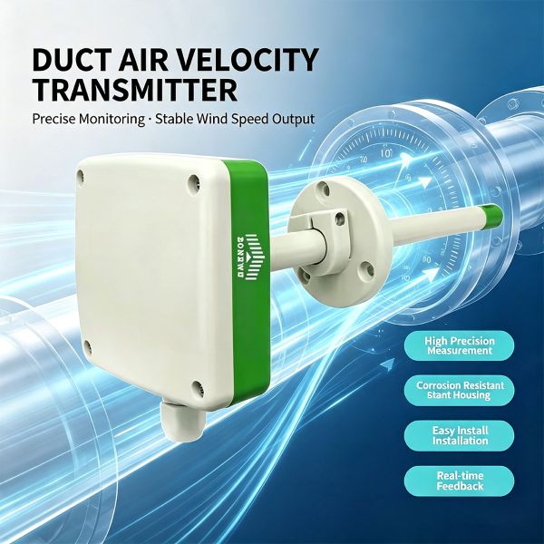
Duct air velocity transmitters are critical equipment for acquiring airflow data in ventilation, environmental protection and industrial exhaust monitoring projects. Improper selection may cause measurement deviations, system incompatibility, or even equipment damage. The following outlines key selection criteria across five dimensions to support sound decision-making.
1. Determine Measured Medium and Measuring Range
-
Medium Type: Clarify the gas composition inside the duct — ordinary air, oil-laden flue gas, nitrogen or other inert gases? Different media impose distinct requirements on sensor materials and protection ratings. Probes resistant to corrosion shall be selected if corrosive components exist.
-
Flow Velocity Range: The common measuring range is 0~30 m/s with a typical resolution of 0.1 m/s. Estimate the normal and peak flow velocity inside the duct before selection. An undersized range will trigger overflow, while an excessively wide range reduces resolution at low flow speeds. For sites with frequent low airflow (<1 m/s), prioritize transmitters with low starting wind speed.
-
Accuracy Specifications: Typical accuracy is ±(0.2 + 2%FS) m/s. For instance, the error is approximately ±0.4 m/s at 10 m/s. Verify compliance against allowable error limits for process control or environmental monitoring.
2. Select Power Supply Mode and Power Consumption Grade
-
DC Power Supply: Most transmitters support wide-range DC input (e.g. 10~30 V) with low power consumption (around 0.5 W), suitable for centralized power supply systems.
-
AC & DC Dual-Supply: Certain models accept 24 V AC or 19~30 V DC with slightly higher power consumption (around 2.4 W), ideal for sites with uncertain power supply sources.
-
Selection Recommendation: If a DC power cabinet is available on site, DC models are preferred to cut power consumption and simplify wiring. If only alternating current is accessible, choose AC/DC compatible transmitters or deploy external power modules.
3. Verify Communication Interface and Protocol Compatibility
-
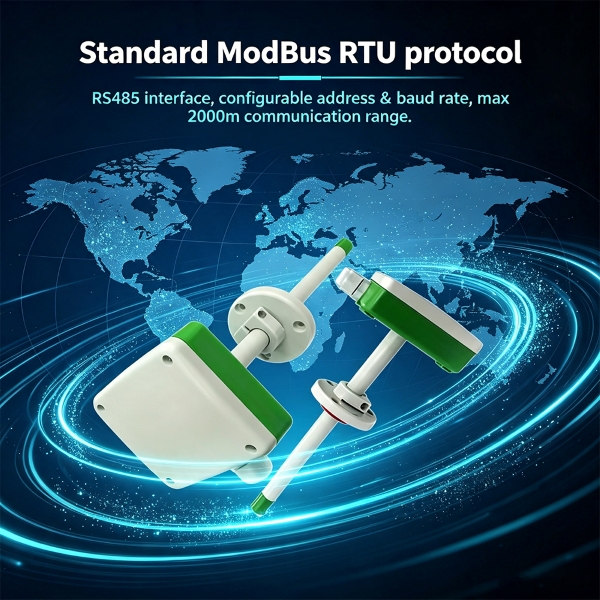
Physical Interface: RS485 serves as the mainstream option, supporting communication distances up to 2,000 meters and allowing multiple devices to be connected in parallel. Pay attention to bus load capacity; repeaters are required when more than 32 nodes are connected.
-
Communication Protocol: ModBus-RTU is most widely adopted on industrial sites, commonly utilizing function codes 0x03 (read) and 0x06 (write). Before selection, confirm that your PLC, data logger or host computer supports this protocol, and check whether register address definitions are clearly documented.
-
Address and Baud Rate: Device addresses shall be configurable (generally 1~254). Supported baud rates should cover multiple options (e.g. 2400~115200 bps) via software configuration or DIP switches. If other instruments share the same bus, assign unique addresses to avoid conflicts.
4. Evaluate Installation Conditions and On-Site Constraints
-
Installation Position: Mount the transmitter on the side or bottom of the duct. Top-down installation is strictly prohibited to prevent condensation water ingress. Drill holes on the duct wall (standard aperture approx. 20 mm) and secure the unit via flanges or threads.
-
Direction Markers: Arrows are printed on the transmitter housing. During installation, align the arrow fully with the airflow direction; misalignment will lead to severely low or even negative readings.
-
Straight Pipe Section Requirements: To mitigate turbulence induced by elbows, valves and other flow obstructions, install the device on straight pipe sections no less than 5 times the pipe diameter downstream of elbows. If space is limited, increase measuring points and adopt average readings.
-
Ambient Temperature: The circuit operating temperature range is typically -40 ℃ ~ +60 ℃. Wide-temperature variants or protective enclosures are required for sites beyond this range.
5. Check Demand for Auxiliary Air Volume Calculation
If real-time air volume (m³/h) is required in addition to air velocity, select transmitters that support duct cross-sectional area configuration. The device automatically converts velocity to air volume internally using the formula: Wind Speed × Cross-sectional Area × 3600 / 10000, and outputs both integer and floating-point data formats.
Cross-sectional Area Configuration: Parameters are normally written via registers (unit: cm²). For circular ducts, calculate the area using the accurately measured inner diameter; for rectangular ducts, multiply length by width. Incorrect settings directly cause distorted air volume data. Confirm the availability and ease of use of this function during selection.
Summary
Follow this sequence for selection: Measured Medium & Measuring Range → Power Supply Type → Communication Protocol Matching → Installation Feasibility → Air Volume Calculation Demand. It is also advised to prepare commissioning tools (such as USB-to-RS485 converters) and inspect device accessories including certificates and calibration reports. For sites suffering severe frequency converter interference, prioritize models with built-in anti-interference circuits. Finally, set the communication polling interval to ≥200 ms to guarantee stable bus operation.
https://www.zonewuiot.com/rs485_c22